Nitinol Animatronic Eye
This Animatronic Eye Mechanism uses nitinol shape memory wires for simple and silent actuation. I developed a novel PCB to enable precise control and self-sensing feedback for each wire’s position. 3D-printing the mechanism's components has allowed for quick iterative prototyping.
Quick project summary:
Step 1: Defining the project scope and goals
Step 2: Nitinol background research
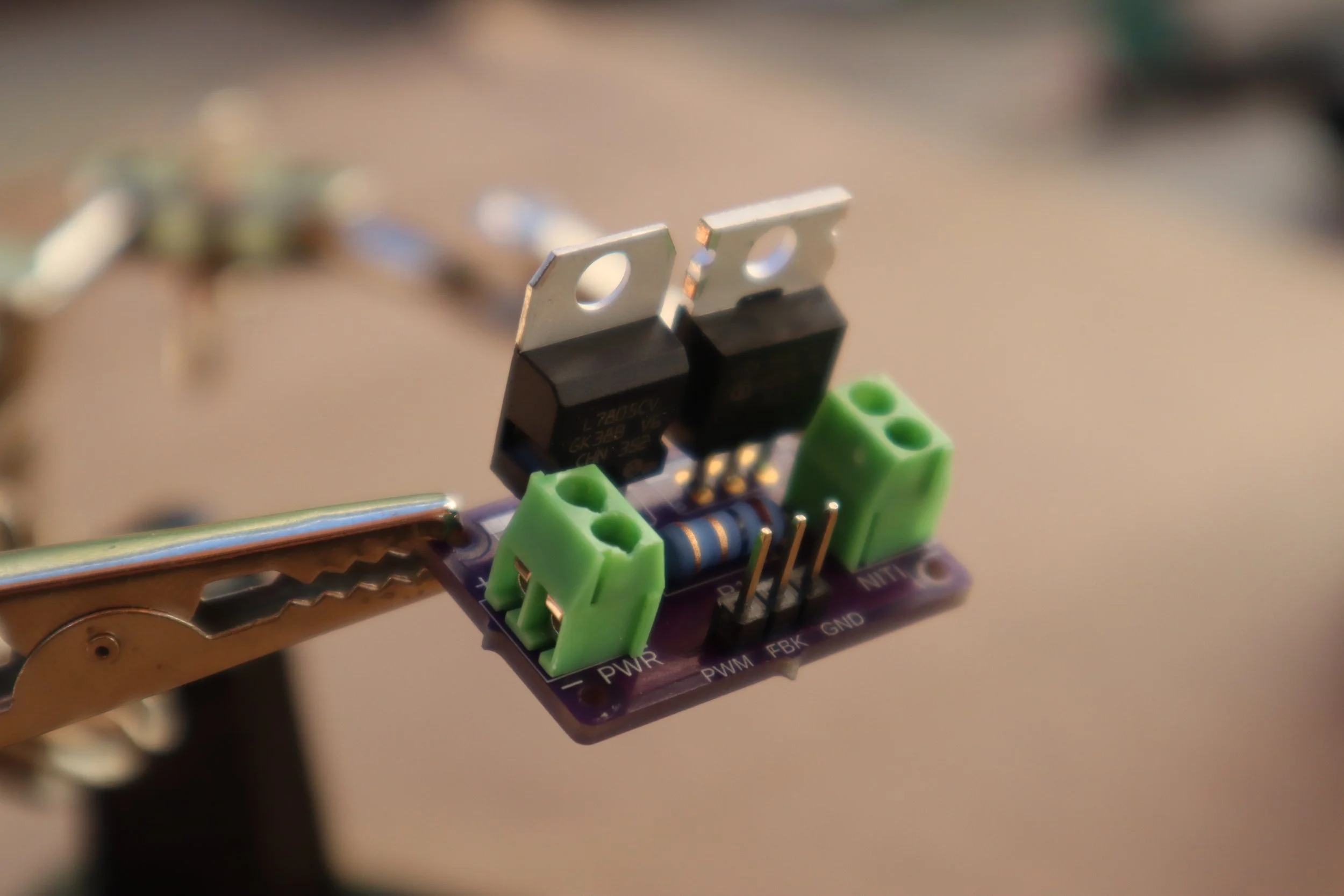
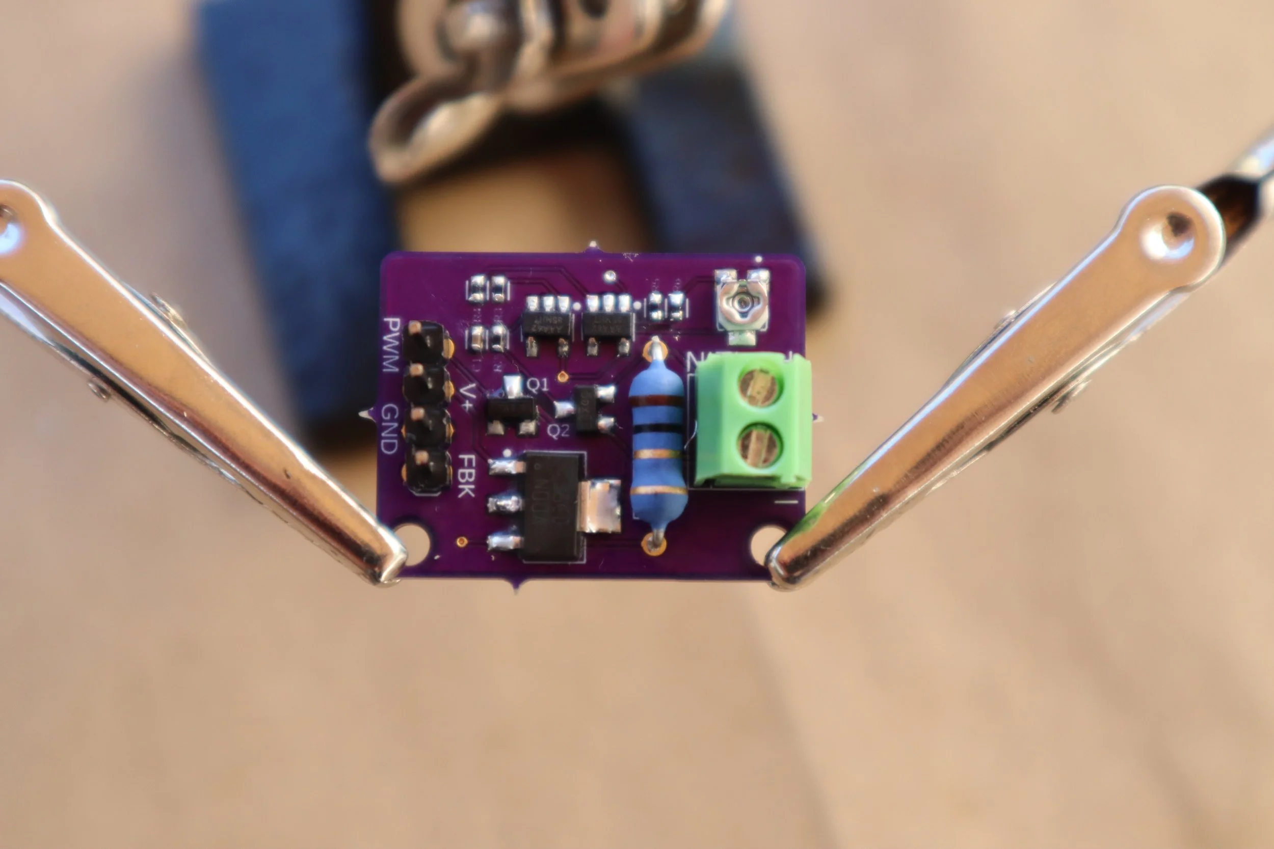
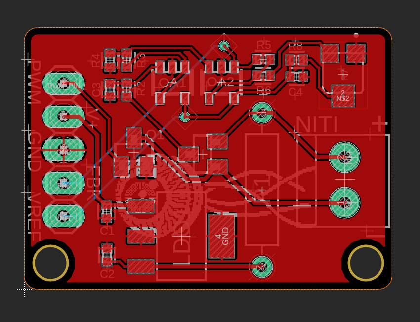
Step 3: Developing the nitinol driver PCB
Nitinol driver PCB Demos
Step 4: Iteratively prototyping the eyeball mechanism
Mechanism Demo
Technical skills employed:
Hardware: Flexinol SMA wire, custom-designed nitinol control PCB, Adafruit PCA9685 PWM breakout, Adafruit ADS1015 ADC breakout, Adafruit Metro Mini
Electronics: Circuit analysis and simulation, Component selection, oscilloscope testing and troubleshooting
Prototyping: SMT reflow soldering, electronics component selection, PCB design and procurement, Design for 3D printing & assembly
CAD: AutoDesk Fusion 360 - parametric modeling, assembly modeling, circuit diagrams, PCB modeling
Fig 1. The cheap servos used in my previous animatronic mask were much too noisy and undermined the overall illusion.
Defining project scope and goals:
I had a ton of fun creating my first animatronic mask a few years ago and have wanted to build a more advanced version. The biggest challenge has been finding affordable, silent servo motors, as the mechanical whir of even the most high-end servos undermines the illusion of animatronics when up close.
I aim to create truly silent animatronics that don’t require expensive components. I’ve decided to start with an eyeball since it’s a natural addition to my mask project and requires 3-dimensional rotational motion, making it an interesting challenge.
I have defined the scope of this design as follows:
Mechanical actuation is inaudible at close proximity (~1 ft)
Costs less than $25 USD for actuator and mechanism components (estimated based on portions of materials used)
Minimum +/- 35 degrees of motion up/down and left/right
Can be powered using commonly available batteries or power supplies
Designed with ease of assembly and maintenance in mind
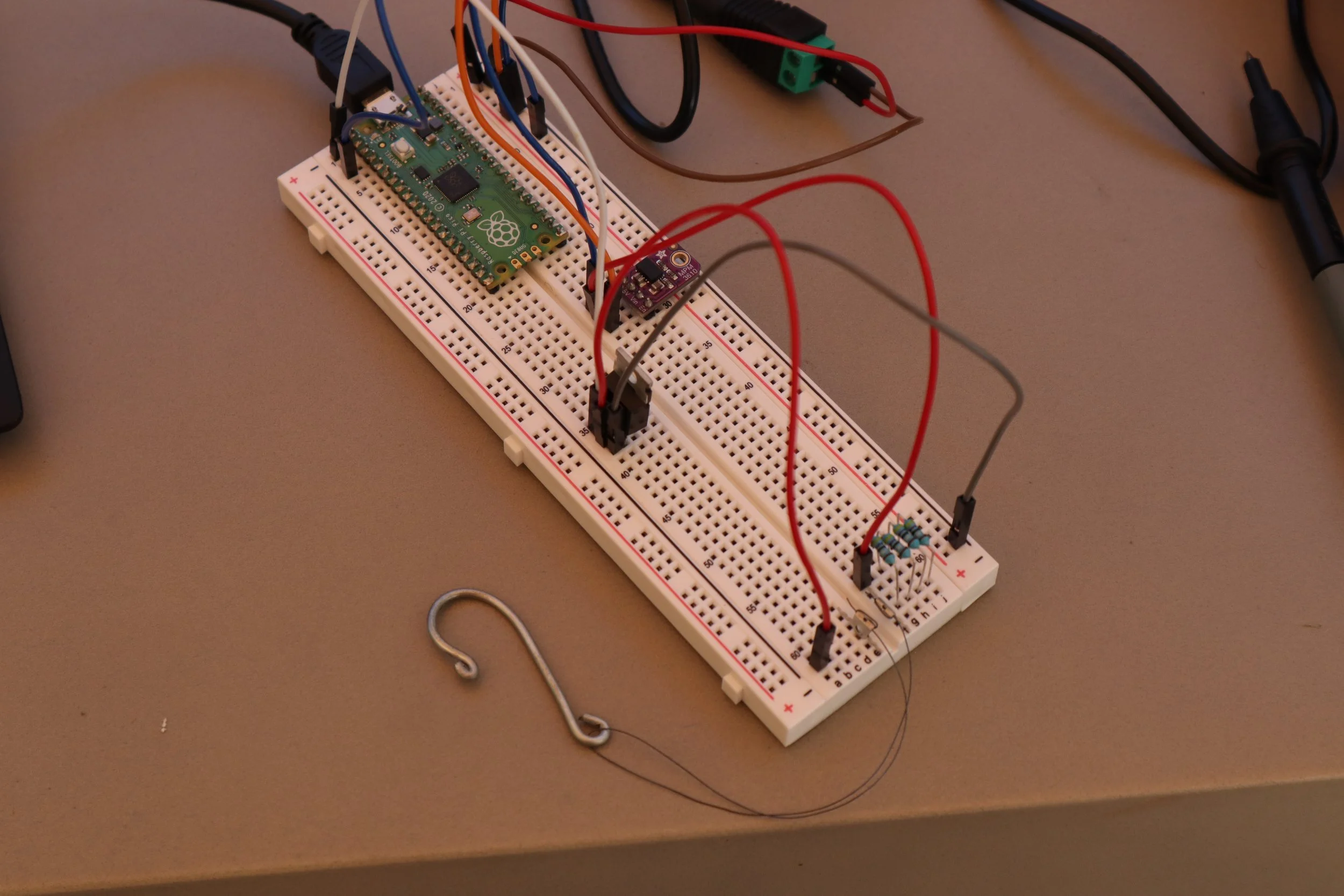
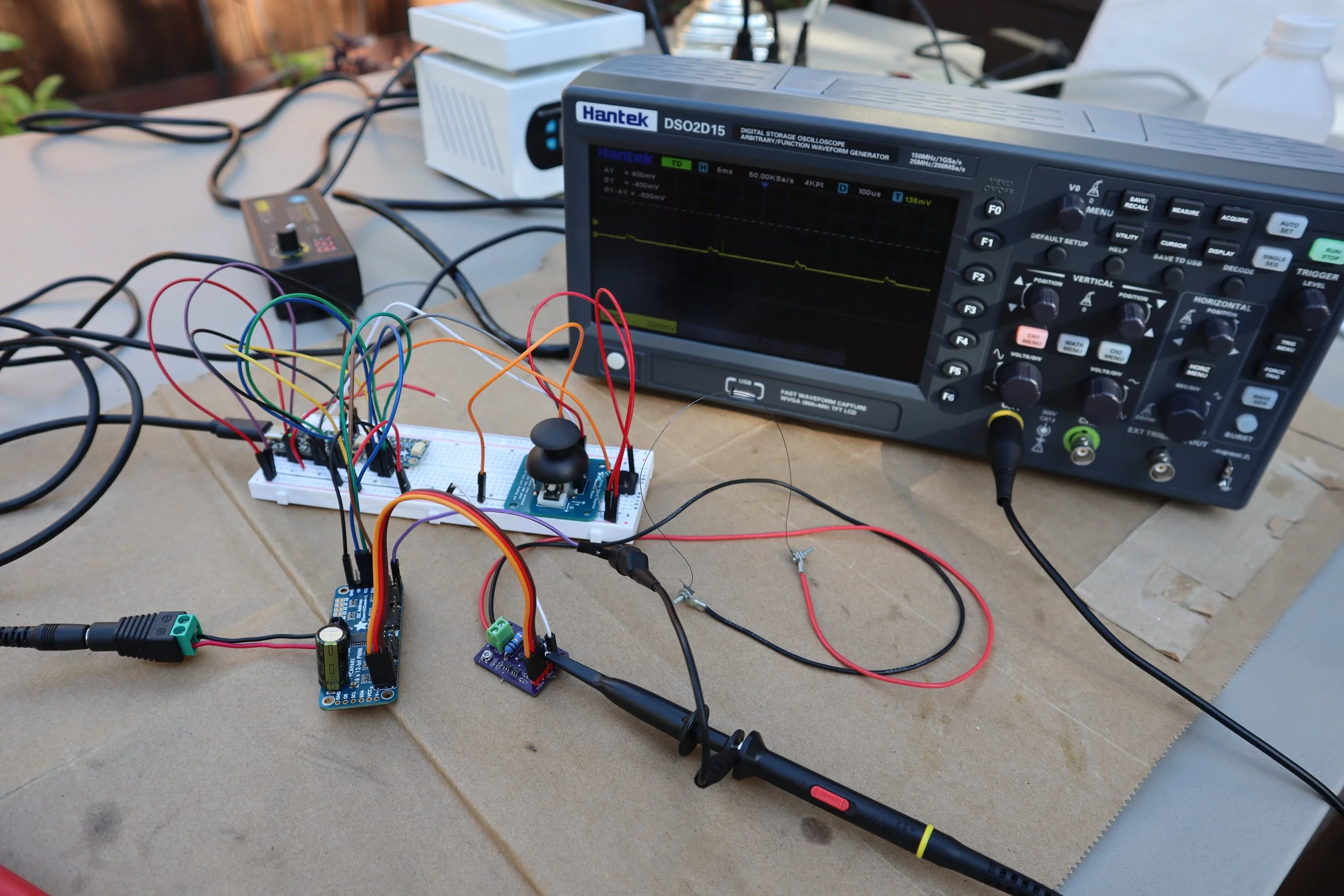
Fig 2. This snapshot shows an early iteration of my test setup. I’m using v1.0 of the nitinol control PCB with two opposing wires.
Nitinol background research:
To begin the process of designing the system for controlling my nitinol actuators, I scoured the internet for information on nitinol’s capabilities and applications, including existing control circuits. I gathered the following information:
Nitinol is a 50% nickel, 50% titanium shape memory alloy. It is flexible at low temperatures when in its martensitic phase (characterized by a more easily deformed crystalline structure). At higher temperatures, the alloy converts to its austenitic phase (rigid, compact crystalline structure), causing it to “remember” and return to a predefined shape.
Commonly used as an actuator in wire form, with 3%-5% axial deflection.
Control circuits heat nitinol wire by passing a current through it, requiring a reliable, constant current source to ensure the wire is not damaged.
PWM signals control wire length proportional to duty cycle and facilitate quicker, more consistent heating.
Actuation time depends on heating/cooling speed, sometimes resulting in considerable hysteresis. Using opposing wires reduces hysteresis for finer control.
Nitinol wire resistance is proportional to length, wire radius, and material phase. If measured accurately, it can provide positional feedback.
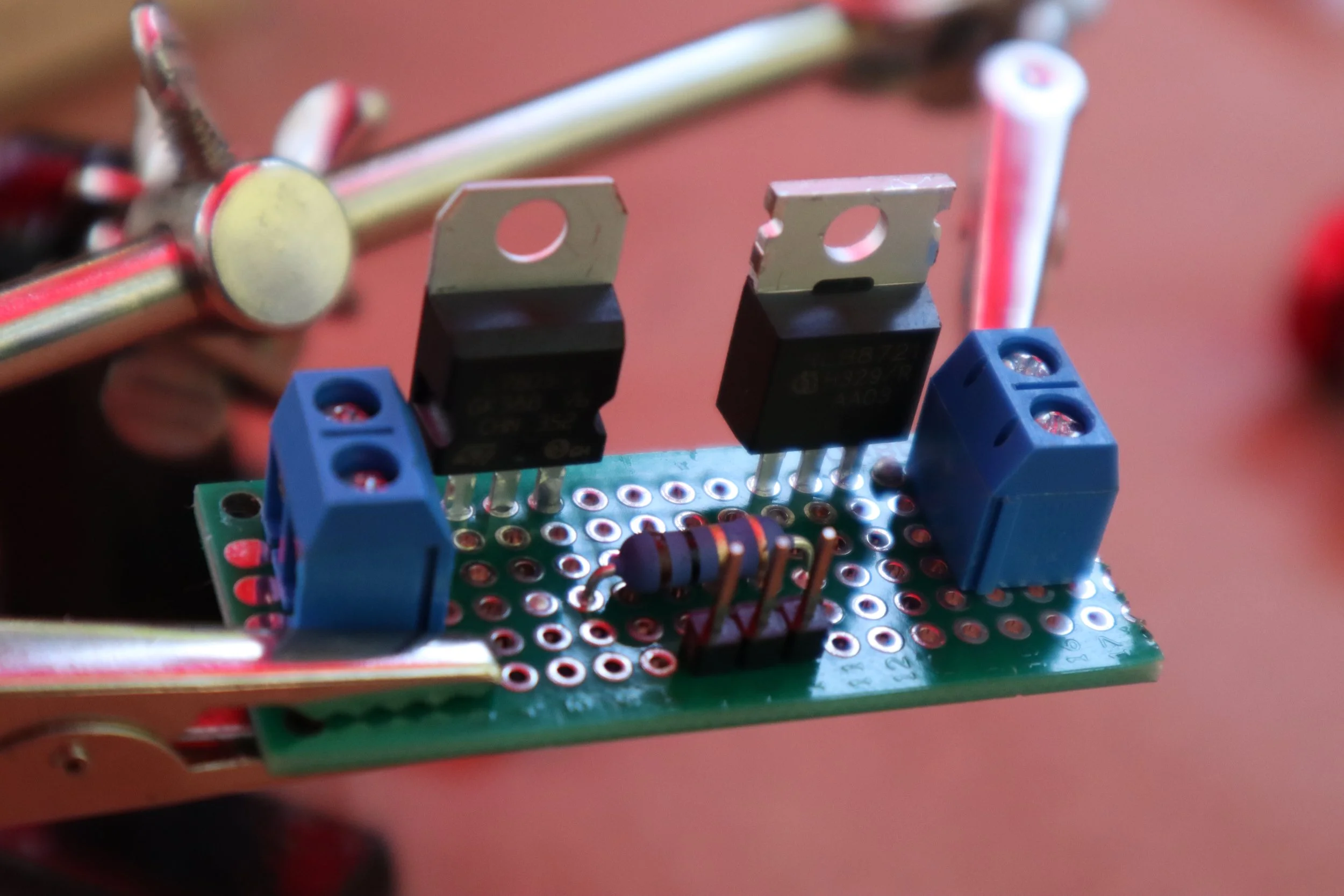
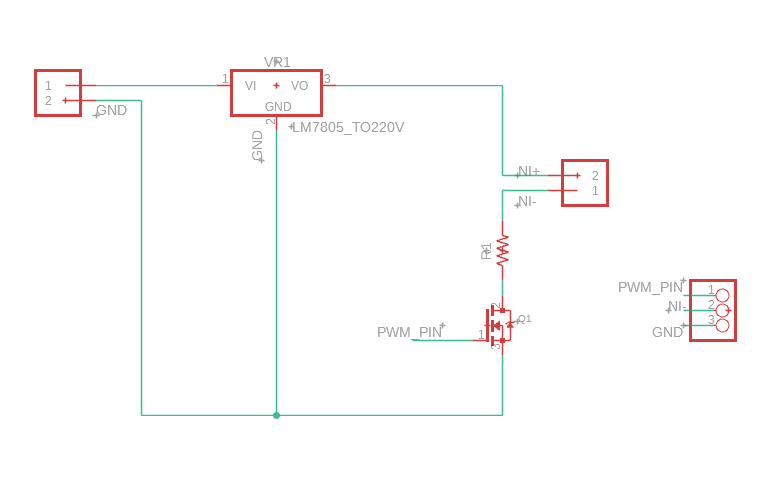
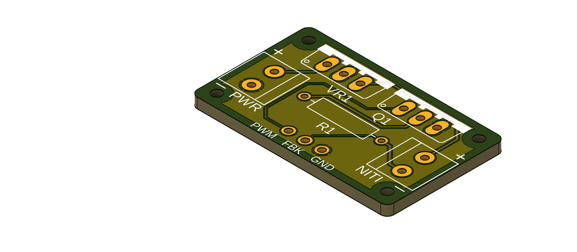
Based on this information, existing research projects, and the few nitinol-based products available online, I developed a novel nitinol driver PCB that integrates PWM control and self-sensing position feedback. This PCB is inexpensive (~$6.23; for details, see the BOM linked in the project summary) and uniquely well-suited for interfacing with hobby development boards like Arduino and Raspberry Pi, making it accessible to regular folks.
Developing the nitinol driver PCB
Here's an example of manually positioning a small cardboard “point” via joystick using four nitinol wires, one in each cardinal direction.
… And here’s an example of the position feedback signal for a single wire. The PWM duty cycle still interferes with the position signal due to a ground voltage difference between the driver PCB and microcontroller (which supplies the PWM and reference voltage for the position feedback signal), but with an amplitude of only ~30mV. As I eliminate this ground voltage difference, the position signal will be fully decoupled from the PWM signal. At the moment, it’s still possible to take consistent measurements provided the position feedback signal is always sampled during the “low state” of the PWM signal. When nitinol wires are used in opposing pairs, one wire can be used to actively pull while the other passive wire is used to measure position.
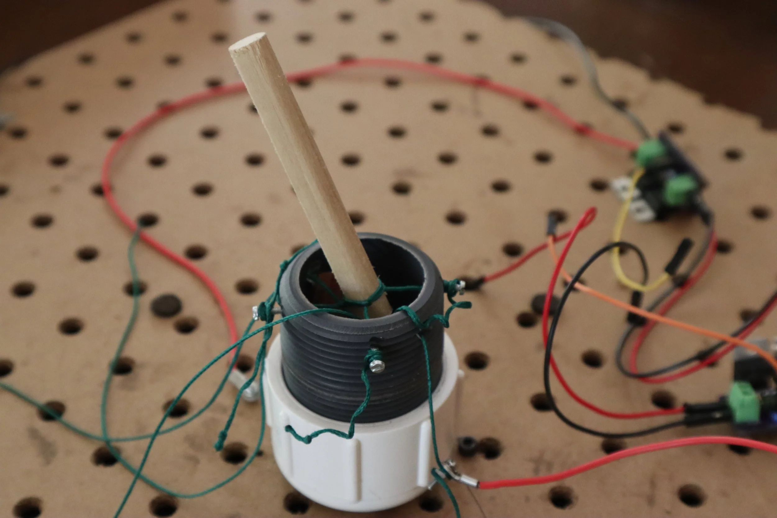
Fig 3. An early concept involved an outer socket holding the eyeball, with wires pulling from inside. There was too much friction for this to be practical.
Iteratively prototyping the eyeball mechanism
I’ve been developing the mechanism for my animatronic eyeball synchronously with the nitinol control PCB so that updates and improvements to either component inform design choices for the other.
Many existing designs for animatronic eyeballs are available online, but all of them use servo motors for actuation. I want to see if I can come up with a mechanism specially suited to nitinol actuation, which means there are several interesting design constraints.
The small range of motion of nitinol wire requires mechanical amplification through levers or something similar.
Nitinol wire can contract itself under power but must be stretched back out with some external force. It will not stay contracted under tension once power is shut off. To save energy, the eyeball mechanism must be able to hold a position without active control by the nitinol.
I’ve used 3D printing to rapidly prototype my design ideas. This has been an invaluable tool, but it has also presented some design constraints based on the material properties of 3D-printed parts. Primarily, the roughness of 3D-printed surfaces has made friction a large factor in my designs.
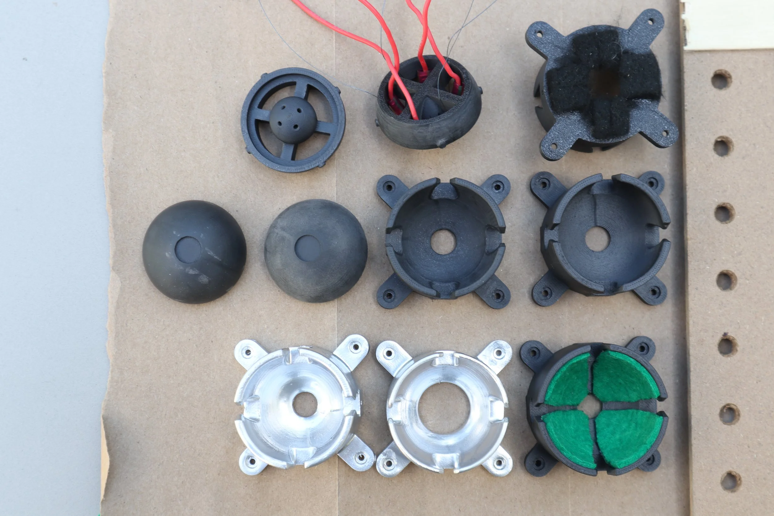
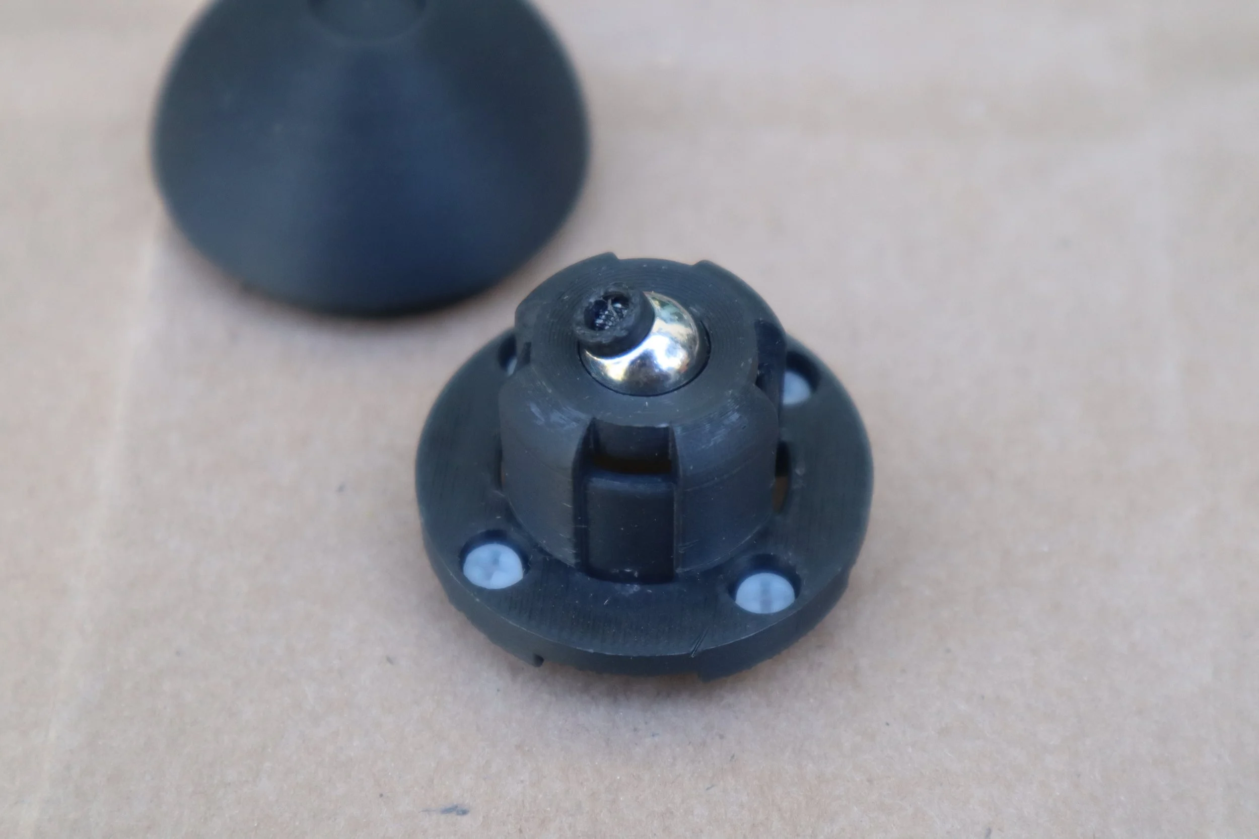
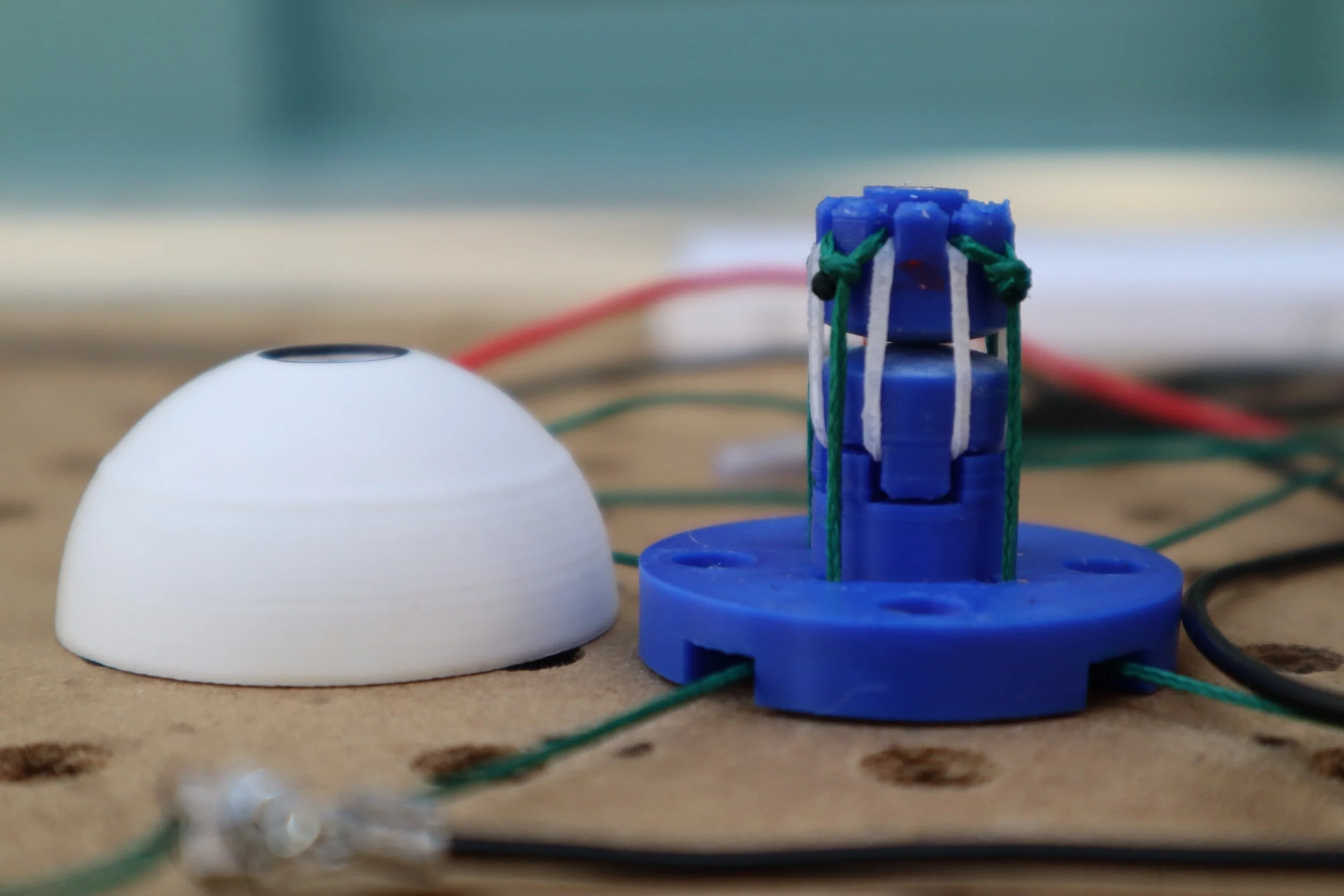
You can see the progression of my mechanism design below:
Developing the eyeball mechanism
The next prototype for this eye mechanism will focus on developing a compact base to reduce the footprint needed for the nitinol wires. I’m also continuing to tinker with ways to attach the nitinol wire to the mechanism so that it’s easy to adjust.


