Zephyr Kite Steering
ZEPHYR KITE STEERING is the second-gen iteration of my kite companion module. Designed for dual-line kites, it transmits positional data and receives steering commands via radio and Bluetooth.
Quick project summary:
Step 1: 1st-gen lessons learned, defining 2nd-gen scope
Step 2: Initial design concept
Step 3: Programming the controllers
Step 4: Modeling the component housing
Step 5: Troubleshooting and testing
Step 6: (In progress) Incorporating test results in current design
Technical skills employed:
Hardware: Adafruit Feather 32u4, Adafruit Feather M0, RFM69HCW Low-frequency radio module, BNO055 IMU, BMP390 altimeter, Continuous Servo w/ encoder, buck-boost converter
Programming: Arduino/C++, continuous servo control, encoder reading, 900MHz radio communication, Bluetooth low-energy communication, PID system control, I2C, SPI, version control (Git)
CAD: AutoDesk Fusion360, parametric modeling, assembly modeling, circuit diagrams, PCB modeling

Fig 1. A view of an early prototype soldered breadboard with a high-torque servo motor and battery attached.
Lessons learned from Gen 1:
Wind speed measurements with a pitot-static tube and differential pressure sensor added unnecessary complications without providing necessary functionality.
DIY-friendly touch screen displays are too finicky and unresponsive to use for sending commands quickly over radio.
CircuitPython on the Raspberry Pi Pico was too slow and resource-greedy for sufficiently fast low-frequency radio communication.
Jumper cables are too unreliable to use in a prototype that will be tested in the field - a soldered breadboard is needed instead.
Definition of Gen 2 Scope:
Able to accurately and precisely measure altitude and orientation.
Able to reliably and quickly steer a dual-line kite so that it actively maintains flight.
Able to transmit and receive messages at a rate sufficient enough to allow for remote steering of the kite.
Able to display measurement and configuration data using a smartphone touchscreen display.

Fig 2. The handheld controller communicates with an iPhone app via BLE but uses low-frequency 900MHz radio to send commands and receive data from the kite module.
Initial Design Concept:
Inspired by the Kitepower system, which uses a dual-line parafoil kite with a pair of winches controlling the tension on each line. the winches are contained in a module which flies suspended beneath the kite. This module is tethered to the ground by a single line.
Steering: After considering many different options for actuation, I chose to use continuous servos because they are compact, strong, easy to control, and allow for an unlimited range of motion. Each servo is responsible for reeling one line of the dual-line kite.
Modules:
Aerial module - tethered to the ground and suspended beneath the kite, this module measures positional data and steers the kite using two continuous servo motors. It transmits measurements and and receives commands via low-frequency 900 MHz radio.
Ground module - converts between radio and Bluetooth communication. It receives Bluetooth commands from a smartphone app, then passes the message along to the aerial module via radio. Similarly, it receives measurements via radio from the aerial module and passes them to the smartphone app using Bluetooth.

Fig 3. To accurately keep track of the continuous servo motors’ positions, I needed to program a custom encoder driver.
Controller programming:
When possible, I used readily available Arduino libraries to save development time.
I created a custom driver for the continuous servos’ position encoders, which included functions to zero the encoder, record measurements, and filter the output.
Both modules use a finite state machine (FSM) model with three states:
Startup - instantiating and configuring the servo, IMU, altimeter, radio and Bluetooth driver objects.
Calibration - calibrating the servo encoders, IMU, and altimeter readings.
Regular functioning - main state in which measurements and steering commands are transmitted between the aerial module and ground modules.
Steering and configuration commands are transmitted between modules irrespective of the current FSM state, meaning the kite can still be controlled when in calibration mode.
To stay within scope, I chose to use a generic Bluetooth communication app developed for smartphones by Adafruit.

Fig 4. The first (failed) iteration of the kite module’s housing. I wanted to maintain low drag regardless of wind direction, but this housing had significant issues that required a redesign.
Modeling Controller Housing:
Using parametric modeling with care and intention and modeling the full assembly in one file, I created a CAD model in Fusion 360 that is easy to update quickly as needed. This dramatically reduces the time needed to implement new ideas and design changes.
First iteration:
Cylindrical shell created the same drag force regardless of orientation in the flow of wind ( assuming wind is mostly perpendicular to the cylindrical surface)
Designed with 3D-printing in mind; large flat surfaces on each component provide a stable base for printing
Electronic components affixed to a removable frame for easier maintenance
Channels in the outer shell to keep the steering lines in place
Second Iteration:
Cube shell, much lighter (approximately 1 lb fully assembled)
Servos are mounted on a rigid central frame, with electronics on each major surface. Harder to assemble but leads to a much more compact housing.
Large wheels
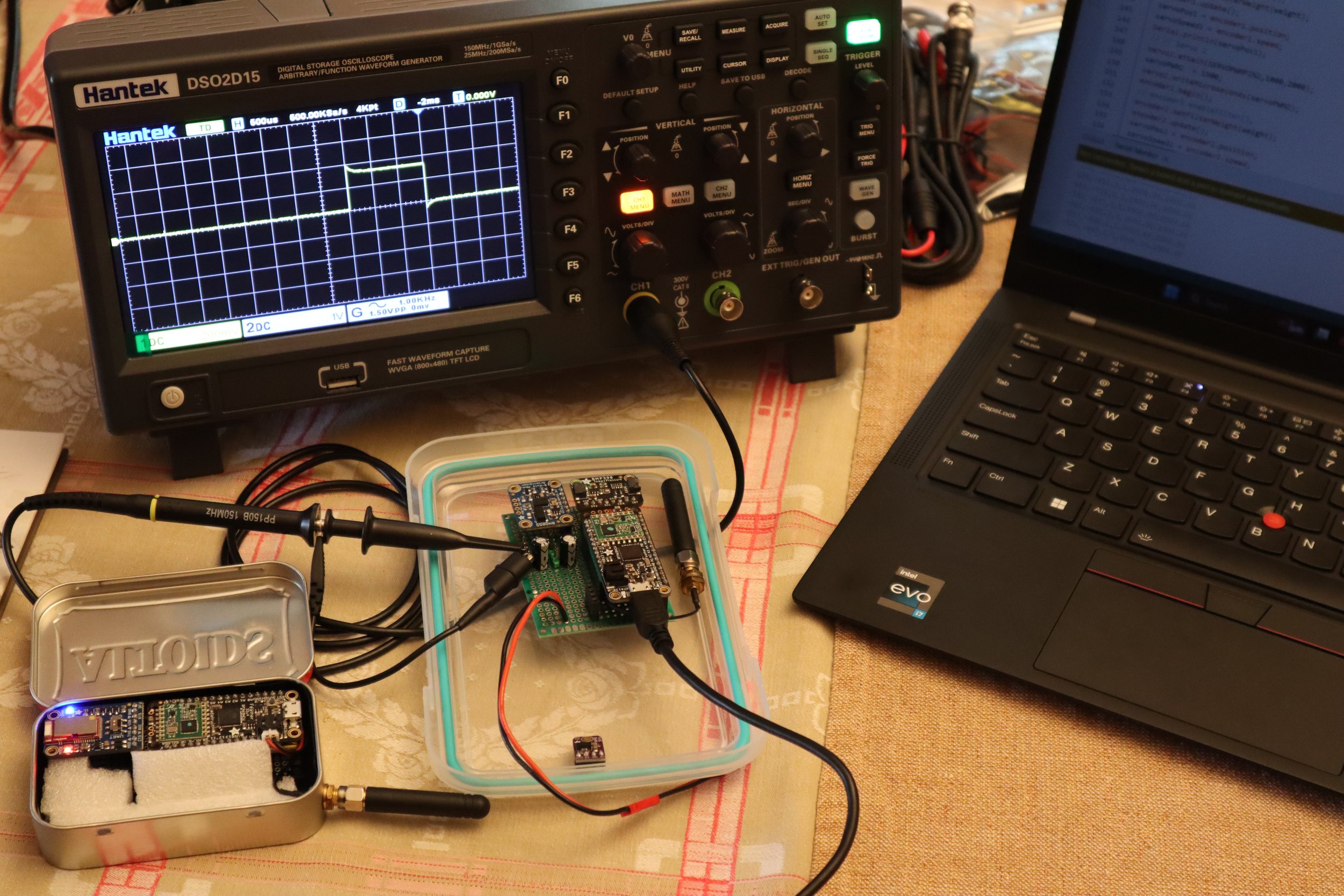
Fig 5. To troubleshoot my persistent servo jitter, I had to isolate different aspects of the system and pinpoint the root of the issue.
Troubleshooting:
During development of my first prototype, I was stumped by a persistent jitter in my servos.
After a first pass of online research into potential causes, I added capacitors to smooth the power supply to each servo. This had no effect, so I decided to start methodically troubleshooting backwards towards the source of the PWM signal that controlled each servo.
Measuring the PWM signal from the microcontroller using my oscilloscope, I immediately observed interference in the signal. This meant the servo jitter was caused by an issue within the microcontroller.
After a second round of online research, I found a few indications that the RFM69HCW library and Arduino servo library could be using the same timer and consequently interrupting each other. Because the servos did not jitter when I disabled the radio object in the code, I figured this must be the issue.
However, I did not see improvement in servo jitter after modifying the timer used by the servo control module or radio control module, shifting the PWM output pins to use supposedly non-conflicting timers, changing to completely different servo and radio control libraries, and even using different radio breakout boards.
I returned to a third round of research and this time posted a very detailed request for help on the Adafruit forum. The forum moderator responded with the cause of my problem as well as a solution; the cause was interrupt contention, which can occur even when different timers are in use because the microcontroller’s processor can only service one interrupt at a time. The solution was to either select a new microcontroller or offload the PWM signal generation to a breakout board.
After weighing both solutions, I decided to offload the PWM signal to an external module to minimize the amount of redesign needed.

Fig 6. Field testing of my kite module has shown promising results, but there are still a few design flaws that need to be resolved.
Field testing:
First Round -
There were too many potential points of failure during the transmission of a steering command from my smartphone to the ground module to the aerial module. As a result, I was often unable to correct the kite’s trajectory in time before crashing.
The aerial module’s housing was too heavy for the kite to lift in all but strongest wind, was difficult to assemble and disassemble, and kite steering lines became easily pinched or knotted around the servo.
Second Round -
Marked improvement in functionality over the first round, but more issues became apparent:
The module could not reel in the steering lines fast enough to respond to quick changes in the kite’s behavior, leading to frequent crashes
The housing eventually broke after repeated crashes, revealing structural weaknesses in the design around the fixtures.

Fig 7. I’ve made significant upgrades to the design throughout this project, but more are still needed before I can call my module complete.
Incorporating Test Results in Current Design:
Added the Adafruit PCA9685 breakout board to outsource servo control; this resolves the timer conflict between radio and PWM control that had interfered with both functions.
Added a pair of physical buttons to the handheld transmitter module to control left/right servos, which replaced the “soft” buttons from the bluetooth interface app; this makes it much less likely that steering commands are dropped during transmission.
Resoldered the steering module breadboard to strengthen connections and add terminals for power distribution and communication pins to the PCA9685 breakout board.
In the process of redesigning the pulleys that are used to reel in the kite’s steering lines; also considering using alternate methods to pull the steering lines.
In the future, I’d like to program a custom smartphone app to fit the specific needs of this project. This would make it much easier to find and interact with configurations and measurements.
Developing the kite module housing
-
![Proof of Concept - Repurposed Tupperware]()
Proof of Concept - Repurposed Tupperware
-
![Housing v1.0 Assembled]()
Housing v1.0 Assembled
-
![Housing v2.0 Model]()
Housing v2.0 Model
-
![Housing v2.0 Assembled]()
Housing v2.0 Assembled
-
![Housing v2.0 Post-crash]()
Housing v2.0 Post-crash
-
![Housing v2.1 (Current)]()
Housing v2.1 (Current)